At 11:41 PM 10/09/2021 -0400, you wrote:
>Hi Guy!
>
>Thanks for the post and interesting. No it's not quite the exact power
>supply but close. However....
>
>Are you *sure* those cards are in the right slots?
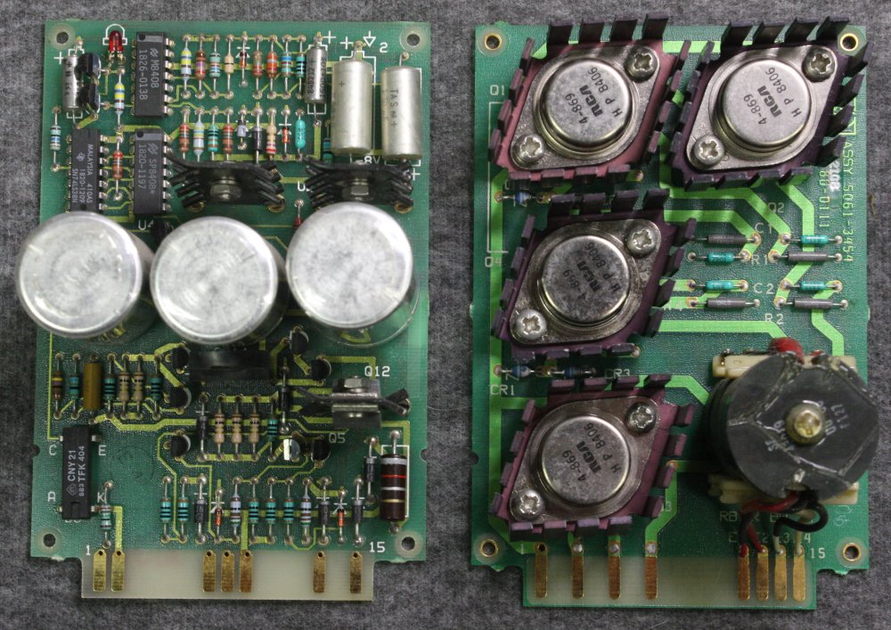
Hmm... I was starting on that system back in Nov 2013.
I'm pretty careful about taking photos of stuff as I take it apart. There's 20
minutes time
between the photo with the PS cover on, and the next with it off, showing the
boards in place.
My memory of that long ago is faded, but I think that 20 minutes was mostly
spent looking at
the  mains voltage selector jumpers, and finding that whoever had originally
converted it to
240V had very nicely saved the now unused jumpers in a small plastic bag shoved
down between
the small transformer and the big blue electro.

This was the first time I'd ever opened the machine, let alone extracted and
opened the PS.
So I am _quite_sure_ the boards are as they were when I got the machine.
Its history - I'd rescued it from a junkyard and imminent destruction. It was
complete with many
I/O cards, two HP tape drives, original HP green racks, but no hard disks.
It had been part of a larger system, with no information about its operational
condition.
Anyway I'd just assumed it was 'previously working, left idle for years.'
Then I'd stored it for some more years, untried. Too busy with work, family,
etc.

Finally got to it. Story:
http://everist.org/NobLog/20131112_HP_1000_minicomputer_teardown.htm

Where I got to, was quickly attempting to run the power supply by itself, to
verify voltages
before reconnecting to the system. It didn't do anything sensible, and I'd
assumed this
was something to do with the PWR CONT IN and BATT INPUT connectors not seeing
expected states.

So I needed a manual. Asking around, I got in contact with Jon Johnston of the
HP Museum in
Victoria Australia. He was away mountain climbing. Later I tried again, in the
meantime he'd
returned then gone climbing in Himalayas again. This time he died there. A good
friend of mine
had also died climbing in the Himalayas, so this project acquired an aversion
factor.

Lacking a schematic, I'd have to disassemble the supply completely and reverse
engineer the
circuits. Not too hard but time consuming. And I was having other life problems.
So the machine got boxed up and shelved - JUST before I'd have started actually
looking
into how the PS was supposed to work. When I would have discovered the board
swap.

Now, looking at the photos, you are right! Those two boards are definitely
swapped.
I just dug out the machine now and am looking at it.

Thinking back to 2013 I recall wondering about the way the TO3 transistor leg
socket-pins
on the board next to the big blue cap, were pressing into the insulating jacket
of the cap.
I recall thinking that didn't seem like a good design.
I'd also spotted the two cards _could_ be interchanged, and written "Pre-Reg"
on the card
that is actually the inverter board. Because it was in the pre-reg slot.
Monkey-see...
Also noted that the lower TO3 heatsink fins were pressing on the wires from
P11.
So I bent the fins up a little bit. No reason to think these problems could be
due to swapped boards!
The slots have "PRE-REG BD" and "INVERTER BD" written in the component
silkscreen, right next
to them, very obviously. Which makes me feel pretty stupid for not realising
the swap,
given how clearly the boards are a small regulator vs power driver.
Also hadn't thought to check the board part numbers against those listed on the
power supply cover.
(IMG_6081.jpg) Which would have immediately revealed they were swapped.

How did that happen? Someone in the last days of the machine's operation,
trying to fix
a fault, giving up, shoving stuff back together carelessly? Or a deliberate
'make it not work
for the auction' thing? (But there was never an auction.) Or did I have a brain
fart,
take the boards out in that 20 minute gap, and put them back in wrong -
violating my
own rule about 'photos first'? (I really don't think so.)

Anyway... So now I know I powered it up with those boards in swapped slots.
Means I _really_
need a schematic. Maaaybe nothing bad happened. But I'd rather check.

All the online PS manuals I've found online are for earlier models. My system
is a 2113E.
Power supply   5061-6615   SN: 2340

The layout of my inverter and pre-reg boards are different than in the earlier
manuals.
Pic: http://everist.org/pics/hp1000_ps/20210911_9766.jpg

I had also found this manual 92851-90001_Sections-IXB-X_Mar-1981.pdf which is
for an
earlier PS than mine. I think it came from bitsavers. I've copied it to the
same folder
as the pics above. Does it match your PS?

I _still_ don't have time to allocate to tracing out the power supply schematic.

Guy


>
>Reason I am asking: When I look at the HP docs they label the
>Pre-regulator board as A3A1. A3A1 also has the red LED. The inverter
>board (the one with the transistors and transformers) is A3A2. Likewise
>the battery charge boards are A3A3, A3A4, and the control board at the
>end is A3A5.
>
>The slots are labeled 1-5 with 1 being closest to the power cord and 5
>being on the output end. A3A5 will only fit in slot 5, and A3A4 has the
>12 volt trim pot that is accessible outside the supply by a cut-out so
>it has to be in slot 4. Slot 3 is not used on my unit because I don't
>have the battery backup circuits.
>
>However in your picture slot 2 has the LED preregulator board and slot 1
>has the one with the transistors and transformers (inverter). So either
>your picture has the parts backwards or someone at HP should go to hell
>for exceptionally bad numbering.
>
>Does your supply work?
>

Further review: Looking at photo IMG_6081.jpg it shows the layouts of
the boards. Specifically A1 is the pre-regulator board pn 5061-3457
which is the one with the caps and A2 is Inverter board PN 5061-3454.

I think if your PS doesn't work one problem is these boards are
backwards. Don't know if that will blow up your supply but interesting
to note...

Hm.... From what I can see it looks like the 120 goes into a transformer
on the bulkhead and is stepped down to 24 volts DC which then feeds
"stuff". I'll start there and see if I get 24dc at the first stage,
which should then be filtered by the caps and sent on to the various
regulators.

C
>> Guy
>>
>>
>>
>>
>> At 09:30 PM 9/09/2021 -0400, you wrote:
>>> Quick question: I've been cleaning out and repairing an HP5061 supply
>>> for a 1000 computer. However I didn't take a picture of the 4 boards
>>> when I pulled them and I want to make sure they go in the right places.
>>>
>>>  From the manual (page 99 of 92851-90001_Sections-IXB_Mar-1981.pdf) the
>>> slots are labeled A6-J1 through A6-J5. Does this mean that:
>>>
>>> J1 is the
>>> J5 is the control board (A3A5)
>>> J4 is a jumper board for +12 adjustments
>>> J3 is unused (battery backup boards)
>>> J2 is the inverter board (A3A2)
>>> J1 is the pre-regulator board (A3A1)
>>>
>>> Seems right but I know how bad things can go :-)
>>>
>>> Thanks!
>>> C
>>>
>