All the glitches are at the beginning of the ALE. There is nothing

there that has any meaning. Things are changing at this time. Not
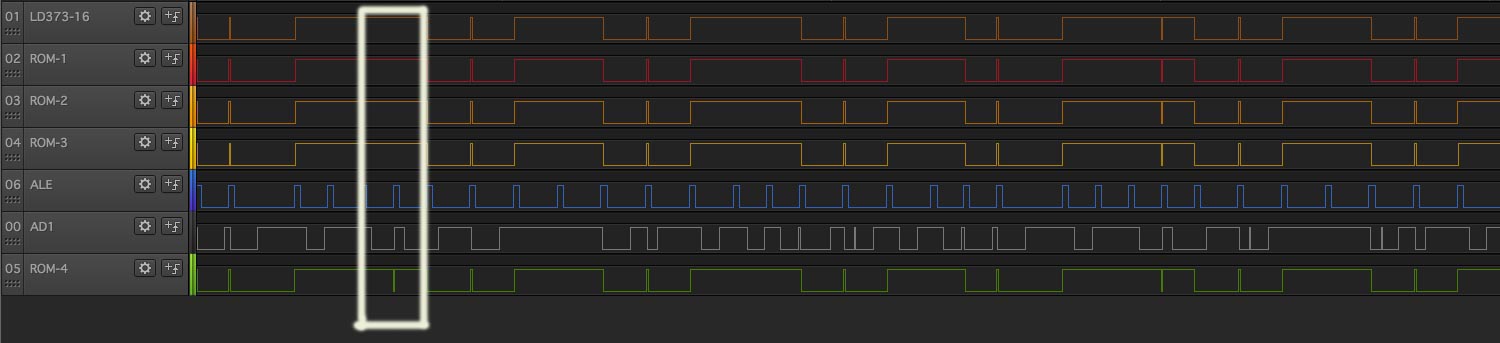
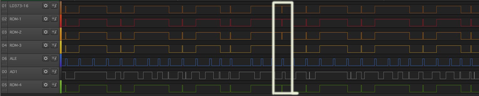
every thing changes at the same rate. That is why they have an

ALE to mark when the address is good. When high, the circuit address

latch is open. When ALE goes low, it captures the address.

You really should be looking at the processor timing diagram and

understand what you are looking at.

Technically a glitch at the beginning of the ALE can last until

some nanoseconds before the falling edge and the circuit would

work fine. These glitches are much shorter than the ALE and

clearly not an issue.

Dwight


________________________________
From: cctalk <[email protected]> on behalf of Jon Elson
<[email protected]>
Sent: Friday, February 3, 2017 6:36:27 PM
To: [email protected]; Discussion@
Subject: Re: Logic Analysers

On 02/03/2017 04:34 PM, Adrian Graham wrote:
> On 03/02/2017 19:43, "Tony Duell" <[email protected]> wrote:
>
>> But that's why I said 'about'. I am doing order-of-magnitude calculations,
>> not trying to design a delay line. I would estimate that between adjacent
>> ICs on the same board you'd get a delay measured in 10's or 100's of
>> picoseconds. That sort of order. So a 25MHz logic analyser, with an
>> effective time resolution of 40ns (if that) is not going to show it.
>>
>> There is no way you're going to get delays of 40ns between adjacent
>> ICs on any reasonable PCB.
> This is the sort of thing I mean:
>
> http://www.binarydinosaurs.co.uk/STCExecutelA1checking.jpg
>
> Watching the A1 address line (no triggers just sampling 6 points) and a
> pulse appears at ROM4 on the falling edge of the ALE signal but not the
> other 3 ROMs or the LS373 flip-flop that's demultiplexing the AD1 pin of the
> 8085. While I was thinking about the possibility of propagation delay I
> noticed this one:
>
> http://www.binarydinosaurs.co.uk/STCExecutelA1checking2.jpg
>
> Pulse missing from ROM3.
First pic, pulses are missing from ROMs 1-3, seen on ROM4.
But, those pulses on ROM4 are really narrow, and may be
noise, or very narrow glitches.  Any time you see really
narrow glitches, especially when they are one LA sample
wide, you have no idea what they actually look like.  The LA
detects that the pulse was there at the instant it sampled
it, but you don't know whether it was 5 ns wide, or 70 ns
wide (with a 40 ns sampling period).  You also don't know
whether they were full-amplitude pulses or runts that just
barely crossed the logic threshold of the analyzer.  So, I'm
not sure what you've shown there actually represents a
problem or not. Especially on the 2nd picture, the pulses
you have highlighted really look like a single sample wide,
and if the logic levels of the analyzer are not exactly the
same, or other slight deviation, it could have missed a
narrow glitch.  Anyway, on old 8-bit micro gear, there may
be plenty of narrow glitches in the 40 ns range, but the
operation of the chips is most likely NOT going to depend on
the circuits responding to such glitches.  I think you are
chasing your tail about these things, and missing a real
malfunction that is not related to this.  Could be EPROM
bits that have faded, one shot capacitors that have changed
value or something.

Jon