Sounds like a good plan, Dennis.

The quadrant stop on my boat is entirely different, so that a single stop
pushes backwards instead of two stops pushing inwards (side to side).  Based on
the photos, I doubt you could configure the style on my boat into your existing
set-up.
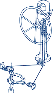
I’m trying to remember what the 35 rudder looks like.  On my boat, the rudder
sits in a skeg.  I had to modify the stop slightly because the rudder turned
far enough with the wheel hard over to crack the edge of the skeg.

Matt Wolford
C&C 42 Custom

From: Dennis C. via CnC-List
Sent: Tuesday, January 29, 2019 9:20 AM
To: CnClist
Cc: Dennis C.
Subject: Stus-List Touche' steering system rebuild - update 1

The original post is below.

My buddy has the pedestal and associated parts for stripping and painting with
AwlGrip.  Aircraft stripper does indeed remove powder coat.
https://drive.google.com/open?id=1OgW3dWk9fqRkoQwowu_fwg5fGehKcd_g

A local rigging shop is duplicating the wire rope cable for me.  The fitting on
the end of the cable that attaches to the chain is apparently called a chain
eye as opposed to a marine eye or aircraft eye.

There seems to be a major change in the rudder stop design.  Touche' is Hull 83.

Thanks to Russ, I have a good example of what a rudder stop should look like.
Note the strong vertical structural member with gussets.  The two plates
mounted to the bottom of the quadrant stop against aluminum plates with rubber
cushions on either side of the vertical structural member.

https://drive.google.com/open?id=1_9BPN1H7YXs586x93QLT8saZVIKJxDSr


Unfortunately, Touche' only has a thin gusset for the rudder tube:

https://drive.google.com/open?id=1jaJX92DAx9vOgV2TWk-fchKrc3k3Zj2h

One other difference is that Touche's quadrant is installed upside down from
the one on Russ' boat.  Go figure.  That doesn't seem to be a big deal.  The
plates will just have to be mounted on the top of the quadrant.

I am going to have to install a vertical structural member.  Still finalizing
the design but it will be similar to Russ' boat.  Going to be very
uncomfortable working in there.

I'm thinking about bonding 3 pieces of marine ply together with the middle
piece shorter so the thing slips down over the existing rudder post gusset.  I
can then through bolt it in place and then tab it to the hull.  I will probably
also make it with the athwartships gussets in place so all I need do is tab
them to the hull.  The gussets are extremely important due to the side loading
of the stops.  The more I do outside the space the easier it will be.

I won't start the job until March after I return from skiing.  I'll document
the process and provide a link.

Dennis C.
Touche' 35-1 #83
Mandeville, LA

On Wed, Jan 23, 2019 at 2:50 PM Dennis C. via CnC-List <cnc-list@cnc-list.com>
wrote:

  Well, I disassembled Touche's steering system yesterday for a loooong overdue
maintenance session.  As in it's never been done in 47 years!  Touche's
steering system is by Morch.

  If you haven't checked your steering system, maybe this will inspire you to
do so.

  Oh, no!  Someone stole my pedestal!!
https://drive.google.com/open?id=12p-nlp8FEwqR0zhDrqlHqxkb7UMa0iSx


  I hope you find this helpful.  I found some items of concern.

  Concern 1.  One of the steering cables had a broken strand.
    a.. See: https://drive.google.com/open?id=1Mu-dmCnPnDFdd5jGHnkBAGSqbGL6jnrw
    b.. The break occurred where the cable made a sharp bend around the
quadrant just before the adjusting stud.
    c.. See:
http://www.bwsailing.com/bw/wp-content/uploads/2014/10/Edson-Quadrant-Dwg.jpg
    d.. A buddy of mine who recently rebuilt the system in his Hans Christian
38 said he saw the same on his
  Concern 2.  Some of the teeth on the chain sprocket were damaged.  This was a
complete surprise.
    a.. See:
https://drive.google.com/open?id=1amngA8i-rm1IkBvn0HhyVGeNrj7T6NSk
    b.. And:
https://drive.google.com/open?id=1a1czFpkvfnyQuFbNIlfHZehhwk-Wyl-8
    c.. This was apparently caused by the way C&C/Morch made stops to limit the
travel of the rudder.  They put a bolt at each end of the chain. The bolts must
have caused the damage when the wheel reached its limit.
    d.. Note the two bolts with washers and nuts through the links of the chain
here:  https://drive.google.com/open?id=1nvJzh8xWDgetBCEE8eeOAtz4-up4ZvCf
  Non-concerns.  The rest of the system looked pretty good.  The idler sheaves
and bracket under the pedestal appeared to be in good condition.  I started to
remove it but decided it will be easier to just pull the pins, remove the
sheaves, clean, lube and re-install.

  The turning sheaves and brackets looked to be in good condition.  (See:
https://drive.google.com/open?id=1jie9IxSqSKorp3FaJtcKjbsNh3nD1TBU).  I cleaned
them and will lube and re-install.

  Next I needed to disassemble the engine control assembly so it can be
stripped and painted.  Using guidance from Chuck, here's that process.
    a.. Back off or remove the two small Phillips head retaining machine
screws.  https://drive.google.com/open?id=1VxT_ApckY55M7xXKoctIShPmIKxgrFUj
    b.. Move one lever COMPLETELY to one side and push the other lever out.
https://drive.google.com/open?id=1nqwnvA1UYDEHFVfuH9xi_-sy6YJrSOLE
    c.. Then remove the other lever.
https://drive.google.com/open?id=1pjlIMBqk3lTdZ0vtSWg6TfnNFOcpXQZY
  Next steps.
    a.. Strip powder coat off the pedestal and associated parts and paint with
AwlGrip.  Buddy of mine has leftover paint from painting his mast.

    b.. Replace both cables.  I'm deciding on this.  Edson's cable and wire
kits look like simple swaged thimble eyes and fine thread eye bolts.  I have a
Nicropress swaging tool, swages and thimbles.  I could make up the wire and buy
the eye bolts.  On the other hand, we have a local rigging shop who could
machine swage nicer replacements.  I think I may ask them for a quote.
    c.. The sprocket.  Hmmmm.  The chain makes a full 180 degree wrap over the
sprocket.  I believe there are plenty of undamaged teeth that will work.  On
the other hand, I could try to get the sprocket off the shaft and have a
machine shop make a new one.  I think that would be a risky option.  First, I'm
not sure how I would remove the sprocket.  It has set screws
(https://drive.google.com/open?id=12GbE75ERXZGgz_NalJ93RcXf6rKvL5fi).  I
removed a small one on the sprocket and a larger one on a collar adjacent to
it.  I suspect there is a keyway on the sprocket.  It showed no signs of
moving.  There are some inventive ways to try to pull the shaft but again, they
all have risk.  Then there's the issue of the bearings.  If I muck up the
bearings, I'm screwed.
    d.. Give some thought to a better way to stop the wheel at the travel
limits.
  Here's the link to the folder with all the pics.
https://drive.google.com/open?id=14-oaTFUoebWqxBo8xeUm9K8tPn7xObKE

  So, again, if you haven't check your steering system, you might want to move
that up your work list a bit.  :)

  Dennis C.
  Touche' 35-1 #83
  Mandeville, LA


--------------------------------------------------------------------------------
_______________________________________________

Thanks everyone for supporting this list with your contributions.  Each and
every one is greatly appreciated.  If you want to support the list - use PayPal
to send contribution --   https://www.paypal.me/stumurray
_______________________________________________

Thanks everyone for supporting this list with your contributions.  Each and
every one is greatly appreciated.  If you want to support the list - use PayPal
to send contribution --   https://www.paypal.me/stumurray