Perhaps some of the confusion here arises because Bragg's Law is not a
Fourier transform.
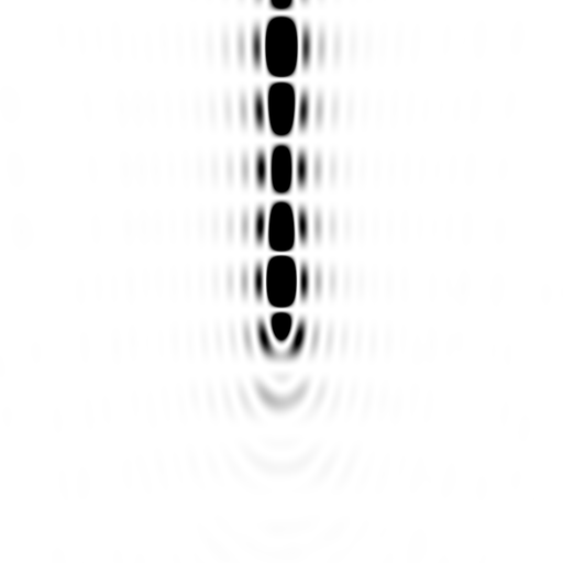
Remember, in the standard diagram of Bragg's Law, there are only two
atoms that are "d" apart. The full diffraction pattern from just two
atoms actually looks like this:
http://bl831.als.lbl.gov/~jamesh/nearBragg/intimage_twoatom.img
This is an "ADSC format" image, so you can look at it in your favorite
diffraction image viewer, such as ADXV, imosflm, HKL2000, XDSviewer,
ipdisp, fit2d, whatever you like. Or, you can substitute "png" for
"img" in the filename and look at it in your web browser. Notice how
there are 9 bands for only 2 atoms? If you look at the *.img file you
can see that the "d spacing" of the middle of each line is indeed 10 A,
5A, 3.33A, and 2.5A. Just as Bragg's Law predicts for n=1,2,3,4 because
the two atoms were 10 A apart ("d" = 10 A) and the wavelength was 1 A.
But what about the corners? The 2.5 A band reads a "d-spacing" of 1.65
A at the corners of the detector! Also, if you look at the central
band, it passes through the direct beam ("d"=infinity), but at the edge
of the detector it reads 2.14 A! Does this mean that Bragg's Law is
wrong!?
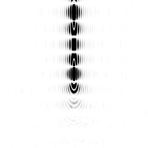
Of course not, it just means that Bragg's Law is one dimensional.
Strictly speaking, it is about "planes" of atoms, not individual atoms
themselves. The Fourier transform of two dots is indeed a series of
bands (an "interference pattern), but the Fourier transform of two
planes (edge-on to the beam) is this:
http://bl831.als.lbl.gov/~jamesh/nearBragg/BraggsLaw/20A_disks.img
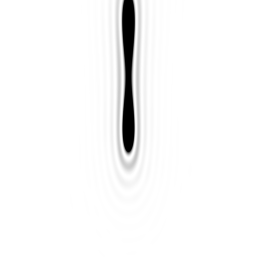
What? A caterpillar? How does that happen? Well, it helps to look at
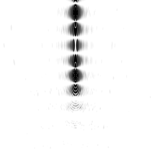
the diffraction pattern of a single plane:
http://bl831.als.lbl.gov/~jamesh/nearBragg/BraggsLaw/20A_disk.img
I should point out here that I'm not modelling an infinite plane, but
rather a disk 20A in radius. This is why the edge of the caterpillar
has a "d-spacing" of 40 A. If it were an infinite plane, its Fourier
transform would be an infinitely thin line, visible at only one point:
the origin. Which is not all that interesting. The "halo" around the
main line is because the plane has a "hard" edge, and so its Fourier
transform has "fringes" (its a "sinc" function). The reason why it does
not run from the top of the image to the bottom is because the Ewald
sphere (a geometric representation of Bragg's law) is curved, but the
Fourier transform of a disk is a straight line in reciprocal space.
By giving the plane a finite size you can more easily see that the
diffraction pattern of a stack of two planes is nothing more than the
diffraction pattern of one plane, multiplied by that of two points.
This is a fundamental property of Fourier transforms: convolution
becomes a product in reciprocal space. Where "convolution" is nothing
more than "copying" an object to different places in space, and in this
case these "places" are the two points in the Bragg diagram.
But, still, why the caterpillar? It is because the Ewald sphere is
curved, so the reciprocal-space "line" only brushes against it for a few
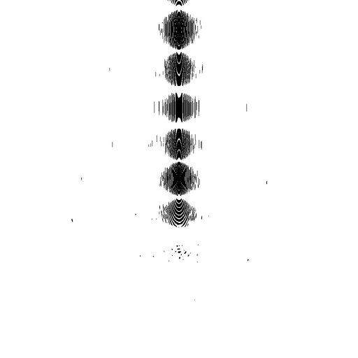
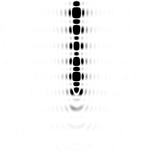
orders. We can, however, get more orders by tilting the planes by some
angle "theta", such as the 11.53 degrees that satisfies n*lambda =
2*d*sin(theta) for n = 4. That is this image:
http://bl831.als.lbl.gov/~jamesh/nearBragg/BraggsLaw/tilted_20A_disks.png
Yes, you can still see the caterpillar, but clearly the 4th "spot" up is
brighter than all but the 0th-order one. The only reason why it is not
identical in intensity is because of the inverse square law: the pixels
on the detector for the 4th-order "reflection" are a little further away
from the "sample" than the zeroeth-order ones.
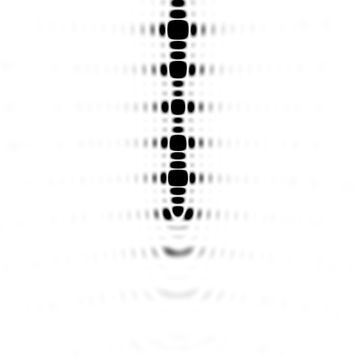
 As the planes get wider:
http://bl831.als.lbl.gov/~jamesh/nearBragg/BraggsLaw/tilted_20A_disks.png
http://bl831.als.lbl.gov/~jamesh/nearBragg/BraggsLaw/tilted_40A_disks.png
http://bl831.als.lbl.gov/~jamesh/nearBragg/BraggsLaw/tilted_80A_disks.png
http://bl831.als.lbl.gov/~jamesh/nearBragg/BraggsLaw/tilted_160A_disks.png
the "caterpillar" gets thinner you see less and less of the n=1,2,3
orders. For an infinite pair of planes, there will be only two
intersection points: the origin and the n=4 spot. This is not because
the intermediate orders are not there, they are just not satisfying the
"Bragg condition", and neither are their "fringes".
Of course, with only two planes, even the infinite-plane spot will be
much "fatter" in the vertical. Formally, about half as "fat" as the
distance between the spots. This is because the interference pattern
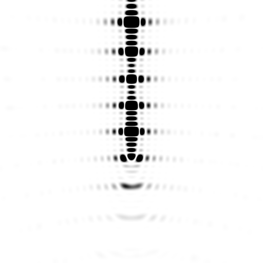
for only two points is still there. But if you have three, four or five
planes, you get these:
http://bl831.als.lbl.gov/~jamesh/nearBragg/BraggsLaw/tilted_20A_disk.png
http://bl831.als.lbl.gov/~jamesh/nearBragg/BraggsLaw/tilted_20A_disks.png
http://bl831.als.lbl.gov/~jamesh/nearBragg/BraggsLaw/tilted_20A_3disks.png
http://bl831.als.lbl.gov/~jamesh/nearBragg/BraggsLaw/tilted_20A_4disks.png
http://bl831.als.lbl.gov/~jamesh/nearBragg/BraggsLaw/tilted_20A_5disks.png
Where you can see the "subsidiary maxima" in between the "Bragg peaks".
There has been some excitement about these of late for phasing XFEL
images, and they only show up for crystals that are relatively few unit
cells wide. That is, the number of subsidiary maxima is proportional to
the number of planes (stacks of unit cells), but their intensity fades
relative to the Bragg peaks with the square of the number of planes,
which you can confirm with the "img" files and a diffraction image viewer.
How does all this relate to structure factors? Well, actually, it
doesn't. Everywhere on all of these images the structure factor has an
amplitude of one and a phase of zero. This is because there is only one
electron in the "unit cell" here, and all the fancy shapes are actually
due to the "lattice". If we want to talk about a "unit cell" with two
atoms in it, then there are two, overlapping lattices, and they
interfere with each other in the usual "convolution becomes a product"
way. That is, you can calculate the diffraction pattern for two points,
and then multiply that diffraction pattern by that of the "lattice" with
only one electron per unit cell. In this way, you can build up anything
you want, but Bragg's genius was in simplifying all this to a little
rule which tells you how much to turn the crystal to see a given spot.
We sort of take this for granted now that we have automated
diffractometers that do all the math for us, but in 1914 realizing that
the rules or ordinary optics could be applied to x-rays and crystals was
a pretty important step forward.
-James Holton
MAD Scientist

On 8/22/2013 12:57 AM, [email protected] wrote:
Dear James,
thank you very much for this answer. I had also been wondering about it. To
clearify it for myself, and maybe for a few other bulletin board readers, I
reworked the Bragg formula to:

sin(theta) = n*Lamda / 2*d

which means that if we take n=2, for the same sin(theta) d becomes twice as big
as well, which means that we describe interference with a wave from a second
layer of the same stack of planes, which means that we are still looking at the
same structure factor.

Best,
Herman


-----Ursprüngliche Nachricht-----
Von: CCP4 bulletin board [mailto:[email protected]] Im Auftrag von James
Holton
Gesendet: Donnerstag, 22. August 2013 08:55
An:[email protected]
Betreff: Re: [ccp4bb] Dependency of theta on n/d in Bragg's law

Well, yes, but that's something of an anachronism.   Technically, a
"Miller index" of h,k,l can only be a triplet of prime numbers (Miller, W.  (1839). A treatise on
crystallography. For J. & JJ Deighton.).  This is because Miller was trying to explain crystal facets, and facets don't
have "harmonics".  This might be why Bragg decided to put an "n" in there.  But it seems that fairly
rapidly after people starting diffracting x-rays off of crystals, the "Miller Index" became generalized to h,k,l
as integers, and we never looked back.

It is a mistake, however, to think that there are contributions from different structure factors in
a given spot.  That does not happen.  The "harmonics" you are thinking of are actually
part of the Fourier transform.  Once you do the FFT, each h,k,l has a unique "F" and the
intensity of a spot is proportional to just one F.

The only way you CAN get multiple Fs in the same spot is in Laue diffraction. Note that the
"n" is next to lambda, not "d".  And yes, in Laue you do get single spots with
multiple hkl indices (and therefore multiple structure factors) coming off the crystal in exactly
the same direction.  Despite being at different wavelengths they land in exactly the same place on
the detector. This is one of the more annoying things you have to deal with in Laue.

A common example of this is the "harmonic contamination" problem in beamline x-ray beams.  Most beamlines use the h,k,l =
1,1,1 reflection from a large single crystal of silicon as a diffraction grating to select the wavelength for the experiment.  This
crystal is exposed to "white" beam, so in every monochromator you are actually doing a Laue diffraction experiment on a
"small molecule" crystal.  One good reason for using Si(111) is because Si(222) is a systematic absence, so you don't have
to worry about the lambda/2 x-rays going down the pipe at the same angle as the "lambda" you selected.  However, Si(333) is
not absent, and unfortunately also corresponds to the 3rd peak in the emission spectrum of an undulator set to have the fundamental
coincide with the Si(111)-reflected wavelength.  This is probably why the "third harmonic" is often the term used to
describe the reflection from Si(333), even for beamlines that don't have an undulator.  But, technically, Si(333) is not a "har
monic" of Si(111).  They are different reciprocal lattice points and each has its own
structure factor.  It is only the undulator that has "harmonics".

However, after the monochromator you generally don't worry too much about the
n=2 situation for:
n*lambda = 2*d*sin(theta)
because there just aren't any photons at that wavelength.  Hope that makes
sense.

-James Holton
MAD Scientist


On 8/20/2013 7:36 AM, Pietro Roversi wrote:
Dear all,

I am shocked by my own ignorance, and you feel free to do the same,
but do you agree with me that according to Bragg's Law a diffraction
maximum at an angle theta has contributions to its intensity from
planes at a spacing d for order 1, planes of spacing 2*d for order
n=2, etc. etc.?

In other words as the diffraction angle is a function of n/d:

theta=arcsin(lambda/2 * n/d)

several indices are associated with diffraction at the same angle?

(I guess one could also prove the same result by a number of Ewald
constructions using Ewald spheres of radius (1/n*lambda with n=1,2,3
...)

All textbooks I know on the argument neglect to mention this and in
fact only n=1 is ever considered.

Does anybody know a book where this trivial issue is discussed?

Thanks!

Ciao

Pietro


Sent from my Desktop

Dr. Pietro Roversi
Oxford University Biochemistry Department - Glycobiology Division
South Parks Road Oxford OX1 3QU England - UK Tel. 0044 1865 275339