Hello,
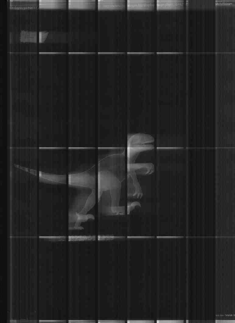
It's a little bit better with these values.
In Genesys_Sensor I have :
regs_0x08_0x0b : {0x00, 0x21, 0x00, 0x00}
regs_0x10_0x1d : {0x02, 0x8b, 0x02, 0x8b, 0x02, 0x8b, 0x20, 0x06, 0x00,
0xff, 0x24, 0x00, 0x00, 0x04}
regs_0x52_0x5e : {0x02, 0x04, 0x02, 0x04, 0x02, 0x04, 0x0a, 0x71, 0x55,
0x00, 0x00, 0x20, 0x41}
In Genesys_Gpo I have :
{0x02, 0x80}{0x7f, 0xe0}

and now in Genesys_Frontend :
{{0x00, 0x2f, 0x07, 0x26}
    , {0x00, 0x00, 0x00}
    , {0x50, 0x50, 0x50}
    , {0x28, 0x28, 0x28}
    , {0x0d, 0x00, 0x00}
    }

Are these value acceptable regarding my log
(http://ggastebois.free.fr/lide90_snoop/UsbSnoop_a4_200dpi.log) ?

I very appreciate your help.

Regards
Guillaume

P.S : attached a sample image with my values.

Pierre Willenbrock a ?crit :
> Guillaume Gastebois schrieb:
>> OK, but via which register is it programmed. I find nothing in GL842
>> datasheet
>> for frontend.
>>
>> regards
>> Guillaume
>>
>
> the analog frontend is programmed through the serial interface accessed
> by address registers 0x50(FERDA)/0x51(FEWRA) and data registers
> 0x46/0x47(FERDDATA)/0x3a/0x3b(FEWRDATA).
>
> I find this sequence in your log:
>
> R/W ! addr ! data  ! WM8199 register
> ----+------+-------+-----------------
>  W  ! 0x04 ! 0x000 ! reset
>  R  ! 0x07 ! 0x041 ! revision number, ==0x41
>  W  ! 0x04 ! 0x000 ! reset
>  W  ! 0x01 ! 0x02f ! Setup reg 1: mode4==0, pgafs=2, selpd=1, mono=1,
> cds=1, en=1
>  W  ! 0x02 ! 0x007 ! Setup reg 2: del=0, rlcdacrng=0, 0=0, vrlcext=0,
> invop=1, muxop=3
>  W  ! 0x03 ! 0x026 ! Setup reg 3: chan=0, cdsref=2, rlcv=6
>  W  ! 0x06 ! 0x00d ! Setup reg 4: fm=0, intm=0, rlcint=1, fme=1,
> acycnrlc=0, linebyline=1
>  W  ! 0x08 ! 0x000 ! Setup reg 5: 0=0, posnneg=0, vdel=0, vsmpdet=0
>  W  ! 0x20 ! 0x050 ! dac value red(offset value)
>  W  ! 0x21 ! 0x050 ! dac value green(offset value)
>  W  ! 0x22 ! 0x050 ! dac value blue(offset value)
>  W  ! 0x23 ! 0x050 ! dac value rgb(offset value)
>  W  ! 0x28 ! 0x028 ! pga gain red(0x28 is a factor of 0.85)
>  W  ! 0x29 ! 0x028 ! pga gain green
>  W  ! 0x2a ! 0x028 ! pga gain blue
>  W  ! 0x2b ! 0x028 ! pga gain rgb
>
>
> all WM81xx(at least where datasheets are available) share a similar
> register layout, with revision 0x41 at address 7. writing to the rgb
> variant of pga gain/dac value results in writes to all the color
> specific registers, so it is not needed.
>
> So, you have in Genesys_Frontend: reg[1]=0x2f, reg[2]=0x07, reg[3]=0x26,
> reg2[0]=0x0d, reg2[1]=0x00, the rest of reg/reg2 =0, all sign[x]=0,
> offset[x]=0x50, gain[x]=0x28.
>
> this does not match anything currently in genesys_devices.c. Just add
> one entry to the Wolfson array, #define a DAC_xxxx to 7 in genesys_low.h
> and put that in your Genesys_Model.
>
> The gain/offset setting should be good for led calibration and will be
> replaced by gain/offset calibration.
>
> After that, get a scan of the calibration area(the area under the
> housing at the parking position). For this, put 0 into the x_offset and
> y_offset in your Genesys_Model. If this turns out to be similar to the
> calibration area of the lide 50, led/offset/gain-calibration should work
> with only minor changes.
>
> Regards,
>   Pierre
>
>
-------------- next part --------------
A non-text attachment was scrubbed...
Name: toto.jpg
Type: image/jpeg
Size: 14210 bytes
Desc: not available
Url :
http://lists.alioth.debian.org/pipermail/sane-devel/attachments/20080204/32c0a175/attachment.jpg