http://www.tapscape.com/apple-electric-car-real-patent/
Apple Electric Car: It's as Real as the Patent
ronaldcarlson | 03, Feb 2015
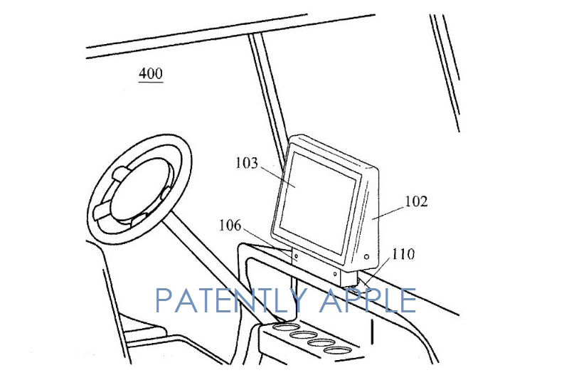
[images
http://www.tapscape.com/wp-content/uploads/2015/02/apple-electric-car.jpg
apple-electric-car

http://www.tapscape.com/wp-content/uploads/2015/02/apple-electric-car-patent.jpg


video
https://www.youtube.com/watch?v=uLUWcnExSA4
iMove concept car
Liviu Tudoran Sep 23, 2010
2nd semester project at IED, Turin. Apple machintosh concept car.
http://www.tudoran.carbonmade.com
http://www.liviutudoran.blogspot.com
]

And, the patent is just a piece of paper… By the time Steve Jobs and Apple
had redefined their fourth and fifth, respectively, universe-denting product
category — Macintosh, PowerBook, iPod, iPhone and iPad — people were already
imagining what an Apple electric car would look like.

Liviu Tudoran’s doodles and renders — image above and video below the fold —
are among the more accomplished visions of the Apple electric car.

Although Cupertino, CA company likely won’t design, build and sell the Apple
electric car, one checkbox item needed before it could has been checked.
Patently Apple reports that the US Patent & Trademark Office has received a
patent for the Apple Electric Car, Inc.

“Is this proof of Apple entering the electric car business? – Of course
not,” writes Patently Apple. “It’s likely just a one in a million fluke that
it appeared on today’s list of granted patents for Apple.”

Yes, the Apple electric car patent is definitely one of the more oddball
patents Apple has been granted. And, as emphatically pointed out by
Patently, this patent is proof of nothing.

Nevertheless, I hope Tudoran and other renewed their interest in the Apple
electric car and produce some nifty renders — I love it…
[© tapscape.com]


http://www.hartfordbusiness.com/article/20150203/NEWS02/302039977
February 3, 2015
Mysterious 'Apple Electric Car, Inc.' files for patent
Apple has long been rumored to be interested in electric cars, so when a
patent was granted Tuesday to "Apple Electric Car, Inc.," that raised more
than a few eyebrows.

The patent, first discovered by blog Patently Apple, isn't necessarily from
Apple, maker of various iGizmos. The patent is for an adjustable mount for a
computerized display in a golf cart. Unless Tim Cook thinks the iGolf is the
wave of the future, the brand name is likely just a coincidence.

Still, Apple and electric cars seem to be a marriage just waiting to happen.

The tech world went nuts a year ago when the San Francisco Chronicle
reported that Tesla CEO Elon Musk had been spotted at Apple's Cupertino,
California, headquarters. (Musk later said it wasn't about an acquisition.)

Wall Street analysts have been hinting for years that Apple could be mulling
an investment in -- or a purchase of -- the electric car company. A company
called ELEKS has developed an Apple Watch app that allows people to control
their Teslas from their wrists.

So what's Apple waiting for? IPhones pretty much do everything except drive
us around anyway. Could this patent be proof that Apple is getting into the
electric car business?

"Of course not," said Jack Purcher of Patently Apple. "It's likely just a
one in a million fluke that it appeared on today's list of granted patents
for 'Apple.' Yet there it was in black and white this morning."

Purcher noted in this blog that the granted patent might have been acquired
by another company, because one of the inventors listed on the patent has no
connection to Apple Electric Car, Inc. The patent allows a golf cart's
display to be viewed by the driver "regardless of whether the user is inside
or outside the golf car," according to the filing.

"Will this possible clue lead to something more substantive down the road?"
Purcher wondered. "Only time will tell."
[© hartfordbusiness.com]


http://www.benzinga.com/news/15/02/5204823/report-apple-electric-car-inc-shows-up-in-granted-patents
Report: 'Apple Electric Car, Inc' Shows Up In Granted Patents
Jayson Derrick , Benzinga Staff Writer
February 03, 2015

According to Patently Apple, there was an "odd-ball" entry in Apple Inc.'s
AAPL 0.49% granted patent list.

Patently Apple on Tuesday discovered a granted patent associated with the
name Apple Electric Car, Inc. However, Apple and car enthusiasts shouldn't
get overly excited just yet as the patent relates to a computer system for
an electric golf cart.

Patently Apple adds, "The granted patent associated with this name Apple
Electric Car, Inc. could have been acquired, as one of the inventors that is
listed as being associated with the invention has no connection to Apple
Electric Car, Inc."

Bottom line, Patently Apple suggests that patent discovery doesn't offer
proof that the company is entering the electric car business.

"Yet there it was in black and white this morning and so we're simply
passing it along as a point of interest at this point in time," the
publication wrote. "Will this possible clue lead to something more
substantive down the road? Only time will tell."
[© benzinga.com]


http://patft.uspto.gov/netacgi/nph-Parser?Sect1=PTO1&Sect2=HITOFF&d=PALL&p=1&u=%2Fnetahtml%2FPTO%2Fsrchnum.htm&r=1&f=G&l=50&s1=8,944,395.PN.&OS=PN/8,944,395&RS=PN/8,944,395
United States Patent    8,944,395
Bonito ,   et al.       February 3, 2015
Golf car and mounting system for a display device incorporated therein

Abstract
A golf car employs a mounting system to attach a display device to the golf
car housing such that the display device is movable so as to facilitate
viewing of a display screen of the display device by a user whether the user
is located inside or outside the golf car. In one embodiment, the mounting
system includes a rigid base member, a swivel member and at least one
extension member. The swivel member mechanically connects the display device
to the rigid base member and facilitates rotation of the display device
about a vertical axis in a range of 0 to about 360 degrees relative to an
initial position of the display device. The extension member is connected to
the rigid base member and facilitates upward and downward movement of the
display device distally from at least one point of attachment of the
mounting system to the golf car housing.
Inventors:      Bonito; Anthony P. (Davie, FL), Pierce; Perry H. (Fort Collins,
CO)
Applicant:
Name    City    State   Country         Type

Bonito; Anthony P.
Pierce; Perry H.
Davie
Fort Collins
FL
CO
US
US
Assignee:       Apple Electric Car, Inc. (Miami Beach, FL)
Appl. No.:      13/558,684
Filed:  July 26, 2012
Prior Publication Data

        Document Identifier     Publication Date
        US 20130193173 A1       Aug 1, 2013
Related U.S. Patent Documents

        Application Number      Filing Date     Patent Number   Issue Date
        12939767        Nov 4, 2010
        12229973        Aug 28, 2008

Current U.S. Class:     248/278.1; 248/276.1; 248/917; 248/921; 248/922;
248/923
Current International Class:    E04G 3/00 (20060101)
Field of Search:        ;248/917-923,278.1,286.1,217.3,276.1 ;296/1.1 ;293/24.1
;224/548
References Cited [Referenced By]
U.S. Patent Documents

5095430 March 1992      Bonito et al.
5179447 January 1993    Lain
5374104 December 1994   Moore et al.
5547248 August 1996     Marechal
6007036 December 1999   Rosen
6179263 January 2001    Rosen et al.
6745065 June 2004       Niwa et al.
Primary Examiner: Sterling; Amy J
Attorney, Agent or Firm: GrayRobinson, P.A. Crilly; Daniel C.
Parent Case Text


CROSS REFERENCE TO RELATED APPLICATIONS
This application is a continuation of U.S. application Ser. No. 12/939,767
filed on Nov. 4, 2010 now abandoned, which is a continuation of U.S.
application Ser. No. 12/229,973 filed on Aug. 28, 2008, now abandoned, and
is incorporated herein by this reference.
Claims


What is claimed is:
1. A golf car for use by a user, the golf car comprising: a display device
for displaying at least play-related information on a display screen
thereof; a golf car housing defining a compartment, the compartment
including at least one seat to be occupied by the user; and a mounting
system for mounting the display device to the golf car housing such that the
display device is movable when attached to the mounting system so as to
facilitate viewing of the display screen by the user whether the user is
located inside or outside the golf car; wherein the mounting system
includes: a rigid base member; a swivel member mechanically connecting the
display device to the rigid base member, the swivel member facilitating
rotation of the display device relative to an initial position of the
display device; and at least one extension member mounted at one end to the
rigid base member and at another end to the golf car housing, the at least
one extension member facilitating movement of the display device distally
from at least one point of attachment of the mounting system to the golf car
housing.

2. The golf car of claim 1, wherein the swivel member facilitates rotation
of the display device in a range of 0 to about 360 degrees relative to the
initial position of the display device.

3. The golf car of claim 2, wherein the at least one extension member
comprises a pair of parallel extension members.

4. The golf car of claim 3, wherein the pair of parallel extension members
comprises a pair of telescoping extension members.

5. The golf car of claim 3, further comprising at least one rigid support
member attached to and separating the pair of parallel extension members,
the rigid support member being positioned between the rigid base member and
the at least one point of attachment of the mounting system to the golf car
housing.

6. The golf car of claim 3, wherein the pair of parallel extension members
extends upward at an angle toward a rear of the golf car.

7. The golf car of claim 1, wherein the at least one extension member
comprises at least one telescoping extension member.

8. The golf car of claim 1, wherein the at least one extension member
extends upward at an angle toward a rear of the golf car.

9. The golf car of claim 1, wherein the mounting system further comprises: a
handle connected to the rigid base member, wherein the handle is usable to
extend and retract the at least one extension member and correspondingly
raise and lower the display device.

10. A golf car for use by a user, the golf car comprising: a display device
for displaying at least play-related information on a display screen
thereof; a golf car housing defining a compartment, the compartment
including at least one seat to be occupied by the user; and a mounting
system for mounting the display device to the golf car housing, wherein the
mounting system includes: a rigid base member; a swivel member mechanically
connecting the display device to the rigid base member, the swivel member
facilitating rotation of the display device relative to an initial position
of the display device; and at least one extension member mounted at one end
to the rigid base member and at another end to the golf car housing, the at
least one extension member facilitating movement of the display device
distally from at least one point of attachment of the mounting system to the
golf car housing.

11. The golf car of claim 10, wherein the at least one extension member
comprises at least one telescoping extension member.

12. The golf car of claim 10, wherein the at least one extension member
extends upward at an angle toward a rear of the golf car.

13. The golf car of claim 10, wherein the mounting system further includes:
a handle connected to the rigid base member, wherein the handle is usable to
extend and retract the at least one extension member and correspondingly
raise and lower the display device.

14. The golf car of claim 10, wherein the swivel member facilitates rotation
of the display device in a range of 0 to about 360 degrees relative to the
initial position of the display device.

15. The golf car of claim 10, wherein the swivel member facilitates rotation
of the display device horizontally about a vertical pivot axis.

16. The golf car of claim 1, wherein the swivel member facilitates rotation
of the display device horizontally about a vertical pivot axis.
Description


BACKGROUND OF THE INVENTION
1. Field of the Invention
The present invention relates generally to golf cars that incorporate
display devices. More particularly, the present invention relates to a golf
car and mounting system for a display device incorporated therein that
facilitate viewing of the display device's display screen by a user
regardless of whether the user is inside or outside the golf car.

2. Description of Related Art
Systems that employ computers on golf cars are well known. Exemplary systems
are disclosed in U.S. Pat. No. 5,095,430; U.S. Pat. No. 5,364,093; U.S. Pat.
No. 5,689,431; U.S. Pat. No. 5,810,680; U.S. Patent Application Publication
No. US 2004/0196181 A1; U.S. Patent Application Publication No. US
2005/0228547 A1; and U.S. Patent Application Publication No. US 2008/0108456
A1. While these patents and publications disclose the use of golf
car-mounted display devices to facilitate the dissemination of information
to golfers and the receipt of information from golfers, none of the patents
or publications disclose mounting of a display device so as to allow a
golfer to view the device's display screen from any position, regardless of
whether the golfer is inside or outside the golf car. For example, none of
the aforementioned patents or publications disclose a display device
mounting system that would allow a golfer to readily view a prerecorded
video of the golfer's swing, which is playing on the display, while the
golfer is standing adjacent his or her ball on the fairway preparing to hit
the golfer's next shot.

There have been numerous approaches to mounting display devices together
with computing devices and/or in vehicles. For example, U.S. Pat. No.
7,133,280 discloses a multi-axial hinge assembly which enables clockwise and
counterclockwise rotation of a display device attached to a hybrid
notebook/tablet personal computer (PC) relative to a vertical axis. However,
the disclosed hinge only allows the display screen to be effectively rotated
through a range of 0-180 degrees from its home position facing the PC's
keyboard. Thus, the disclosed mounting assembly would not permit viewing of
the screen from any location about the PC without also moving the PC.
Additionally, while the hinge also permits 180 degree rotation of the
display screen about a horizontal axis to permit it to be folded in a
clamshell fashion, the mounting assembly does not facilitate substantial
changes in height as may be necessary to compensate for variations in the
contours of golf courses.

As another example, U.S. Pat. No. 6,412,848 discloses a display monitor
system for use in a vehicle. The disclosed display system is mountable to
the ceiling of the passenger compartment of the vehicle and allows rotation
of the display screen about a horizontal axis in a clamshell fashion from
zero to about ninety degrees. The disclosed display system does not
facilitate rotation of the display screen about a vertical axis. Thus, the
disclosed mounting system is designed to allow viewing of the display screen
by users positioned in the rear of the vehicle when the display screen has
been rotated into its open position. Since the disclosed display screen
cannot be rotated about a vertical axis or have its height modified, it is
not readily suited for use by golfers who may want to view the screen from
outside the golf car or when not positioned on only one particular side of
the screen.

As yet another example of a display mounting system, U.S. Pat. No. 6,874,738
discloses a display mounting system configured to provide for vertical
adjustment of a height of a display screen. However, such mounting system
limits vertical and horizontal rotation of the display screen to about 90
degrees. Thus, the mounting system is most suitable for mounting a display
device, such as a liquid crystal display (LCD) or a plasma display, for a PC
or TV set in an indoor environment. Additionally, the limited mobility of
the disclosed mounting system would not make the mounting system readily
suited for use by golfers who could be positioned at various locations
outside a golf car.

As a final example, U.S. Pat. No. 4,220,310 discloses an extensible display
mounting assembly that includes a telescoping pole assembly. The telescoping
pole assembly is extensible to a desired length and includes, at its
extensible end, selectively shaped fixtures for releasably positioning a
magnetically adherable mounting member adapted to support a display device.
The assembly is suitable for magnetically mounting display materials, such
as advertisements, posters, or decorations, at elevated locations above
ground level. The assembly is not robust or rigid enough to support a larger
or heavier display device, such as an LCD or plasma display screen. Further,
the assembly does not provide any mechanism for rotating the display device
horizontally or vertically to facilitate viewing at various angles.

In view of the foregoing, a need exists for a golf car and display device
mounting system for use therein that overcome the shortcomings of the prior
art and facilitate viewing of a display screen mounted to a golf car
regardless of whether a user is inside or outside the golf car.

BRIEF DESCRIPTION OF THE DRAWINGS
The accompanying figures, wherein like reference numerals refer to identical
or functionally similar elements throughout the separate views and which
together with the detailed description below are incorporated in and form
part of the specification, serve to further illustrate various embodiments
and to explain various principles and advantages all in accordance with the
present invention.

FIG. 1 is a perspective view of a display device mounting system with a
display device in a raised configuration in accordance with a first
exemplary embodiment of the present invention.

FIG. 2 is a perspective view of the display device mounting system of FIG. 1
with the display device in a lowered configuration in accordance with an
exemplary embodiment of the present invention.

FIG. 3 is a perspective view of the display device mounting system of FIG. 1
with the display device rotated horizontally counterclockwise about 30
degrees relative to an initial position in accordance with an exemplary
embodiment of the present invention.

FIG. 4 is a perspective view of a portion of a golf car incorporating the
display device mounting system of FIG. 1 and showing the display device in a
raised position in accordance with an exemplary embodiment of the present
invention.

FIG. 5 is a perspective view of a portion of a golf car incorporating the
display device mounting system of FIG. 2 and showing the display device in a
lowered position in accordance with an exemplary embodiment of the present
invention.

FIG. 6 is a perspective view of a portion of a golf car incorporating the
display device mounting system of FIG. 3 in accordance with an exemplary
embodiment of the present invention.

FIG. 7 is a perspective view of a display device mounting system with a
display device in a raised configuration in accordance with a second
exemplary embodiment of the present invention.

FIG. 8 is an exploded perspective view of the display device mounting system
of FIG. 1 in accordance with the first exemplary embodiment of the present
invention.

DETAILED DESCRIPTION
Before describing in detail exemplary embodiments that are in accordance
with the present invention, it should be observed that the embodiments
reside primarily in combinations of apparatus components related to
implementing a golf car and a display device mounting system incorporated
into a golf car. Accordingly, the apparatus components have been represented
where appropriate by conventional symbols in the drawings, showing only
those specific details that are pertinent to understanding the embodiments
of the present invention so as not to obscure the disclosure with details
that will be readily apparent to those of ordinary skill in the art having
the benefit of the description herein.

In this document, relational terms, such as "first" and "second," "top" and
"bottom," and the like, may be used solely to distinguish one entity or
element from another entity or element without necessarily requiring or
implying any physical or logical relationship or order between such entities
or elements. The terms "comprises," "comprising," or any other variation
thereof are intended to cover a non-exclusive inclusion, such that a
process, method, article, or apparatus that comprises a list of elements
does not include only those elements, but may include other elements not
expressly listed or inherent to such process, method, article, or apparatus.
The term "plurality of" as used in connection with any object or action
means two or more of such object or action. A claim element proceeded by the
article "a" or "an" does not, without more constraints, preclude the
existence of additional identical elements in the process, method, article,
or apparatus that includes the element. Additionally, the term "golf car,"
as used herein and in the appended claims, refers to any motorized vehicle,
whether electric, hydrogen, or fuel-propelled, which is used on a golf
course to transport golfers and/or their equipment. The terms "golf car,"
"golf cart," "cart," and "car" are used interchangeably herein.

Generally, the present invention encompasses a golf car and a display device
mounting system for use therein. In accordance with one embodiment of the
present invention, the golf car includes a display device, a golf car
housing, and a mounting system for attaching the display device to the golf
car housing. The display device displays at least play-related or
round-related information to a user or users of the golf car on a display
screen of the device. The mounting system attaches the display device to the
golf car housing such that the display device is movable when attached to
the mounting system so as to facilitate viewing of the display screen by the
user(s) whether the user(s) is located inside or outside the golf car
housing.

In one embodiment, the mounting system includes a rigid base member, a
swivel member mechanically connecting the rigid base member to the display
device, and at least one extension member connected to the rigid base member
and the golf car housing. The swivel member facilitates rotation of the
display device over a range of 0 to about 360 degrees (either full, 360
degree rotation clockwise or counterclockwise, or rotation 180 degrees
clockwise and 180 degrees counterclockwise relative to an initial or home
position to provide about a 360 degree range of rotation). The extension
member(s) facilitates movement of the display device distally relative to
one or more points of attachment of the extension member(s) to the golf car
housing (e.g., up and down at an angle relative to a surface, such as a
dashboard, of the golf car).

By configuring a golf car and its display device mounting system in such a
manner, the present invention enables the display screen of the display
device to be positioned such that users of the golf car can view the display
screen when sitting in the golf car or standing proximate the golf car
(e.g., prior to or after hitting a golf ball). To provide such viewing
flexibility, the mounting system enables the display device, while remaining
secured to the golf car, to be raised and rotated such that a golfer
standing outside the golf car can readily view the display screen. The
mounting system also enables the display device to be lowered so as to not
obscure the view of a user driving the golf car when the golf car is in
motion.

The present invention can be more readily understood with reference to FIGS.
1-8, in which like reference numerals designate like items. FIGS. 1 and 8
depict a display mounting system 100 for use in a golf car to attach a
display device 102 to a housing of a golf car in accordance with a first
exemplary embodiment of the present invention. The display device 102 may be
a liquid crystal display (LCD), a plasma display, a dot matrix display, a
transreflective backlit display, or any other display technology that
enables viewing of textual, graphical, and/or video information. The display
device 102 may display a variety of information, including, but not limited
to: (a) golf play-related information, such as an electronic score card,
distance-to-the-hole information, a layout of the current hole and/or the
entire golf course, a video flyover of the current hole, a notepad, a list
of clubs, tee times, and/or leader boards; (b) advertisements; (c)
electronic commerce information; (d) stock reports; (e) sports scores; (f)
news headlines; and any other textual, graphic or video information that may
be of interest to a golfer or other user. If the display device 102, or the
control device (not shown) from which the display device 102 receives its
information, is configured with an appropriate wireless receiver and
television signal (e.g., MPEG) decoder, the display device 102 may also
display live television in addition to or in place of the other displayed
information. Other exemplary information that may be displayed on the
display device 102 is disclosed in U.S. Patent Application Publication No.
US 2008/0108456 A1, which is hereby incorporated by this reference. The
display device 102 includes a display screen 103 on which the information is
displayed by the display device 102.

According to the embodiment of FIGS. 1 and 8, the exemplary mounting system
100 includes a swivel member 104, a rigid base member 106, and a pair of
extension members 108, 109. The swivel member 104 mechanically connects the
display device 102 to the rigid base member 106 so as to permit the display
device 102 to be horizontally rotated about a vertical pivot axis 113. In
one embodiment, the swivel member 104 includes a metal or plastic
cylindrical member 802 positioned within a circular or cylindrical opening
801 in the rigid base member 106. The opening 801 may be fitted with a
plastic sleeve that snugly surrounds the cylindrical member 802 when the
cylindrical member 802 is positioned within the opening 801. The snugness or
friction between the cylindrical member 802 and the plastic sleeve is
preferably such that after the display device 102 has been rotated to a
desired position, the display device 102 remains in that position until
moved by the user. This embodiment facilitates approximately 360 degree
horizontal rotation of the display device 102 in either or both directions.
In an alternative embodiment, the cylindrical member 802 may include a pin
or other stop member (not shown) that would fit into a groove in the wall of
the opening 801 so as to permit clockwise and counterclockwise horizontal
rotation of the display device 102 from 0 degrees to about 180 degrees,
thereby providing about 360 degrees of horizontal rotation of the display
device 102 relative to its initial or home position. In the alternative
embodiment, the stop member would prevent the swivel member 104 from being
rotated beyond the intended approximately 180 degrees in each direction.

In a further embodiment, the swivel member 104 may be multi-axial, thereby
facilitating both horizontal rotation as discussed above, as well as
vertical rotation of the display device 102 about a horizontal axis 115 that
is substantially perpendicular to the vertical axis 113. In one embodiment,
the swivel member 104 facilitates rotation of the display device 102 about
the horizontal axis 115 in the range of 0 to about 90 degrees in a direction
opposite the display screen 103, where the zero degree reference corresponds
to the display device 102 being fully upright. In an alternative embodiment,
the swivel member 104 facilitates approximately 180 degree rotation of the
display device 102 about the horizontal axis 115. The swivel member 104 may
be implemented using a multi-axial hinge, such as the hinge disclosed in
U.S. Pat. No. 7,133,280 B2, which is incorporated herein by this reference,
modified to permit approximately 180 degree rotation about the vertical axis
113 in both the clockwise and counterclockwise directions relative to a home
position. The swivel member 104 may be alternatively implemented using a
ball and socket mechanism, a pivoting set of arms, or a set of parallel or
scissors-style linkages.

The rigid base member 106 supports the swivel member 104 and may be
fabricated as a metal or plastic (e.g., polyvinylchloride (PVC)) bar or tube
sufficient in length to allow attachment of the base member 106 to the pair
of parallel extension members 108, 109. The base member 106 may be extruded
or constructed using any other known fabrication method. In one embodiment,
the base member 106 is a hollow structure fabricated from approximately
1/8'' inch (approximately 3.2 millimeter) thick metal or plastic that
defines a cavity in which the swivel member 104 is positioned and connected
to the base member 106. In an exemplary embodiment, the base member is
approximately 10 inches (approximately 25.4 centimeters) long by
approximately 2 inches (approximately 5.1 centimeters) wide. The base member
106 may optionally include or be connected to a handle 105 to assist a user
of a golf car containing the mounting system 100 in raising and lowering the
display device 102.

The extension members 108, 109 are oriented generally parallel to one
another and are connected in a conventional manner to the base member 106 to
facilitate movement of the display device 102 distally from points of
attachment of the extension members 108, 109 to the golf car housing. An
exemplary golf car containing the mounting system of FIG. 1 is discussed in
more detail below with respect to FIG. 4.

In one embodiment, each of the extension members 108, 109 is a telescoping
extension member that includes an outer tube 110 and an inner tube 111.
Alternatively, the extension members 108, 109 may be implemented using any
other mechanical, electric, pneumatic, or hydraulic means, such as, but not
limited to, pivoting or sliding rails or arms, accordion or scissors-style
arms, drawer slide, four or more bar linkages, magnetic levitation, cables
or belts, drive screws, pneumatic cylinder ball detent, electronic solenoid,
and mechanical clamps.

When the extension members 108, 109 are implemented as telescoping members,
the inner tube 111 moves in and out of a chamber defined by the outer tube
110 responsive to a force exerted on the inner tube 111. The force may be
manual, such as when a user pulls up or pushes down on the handle 105, the
display device 102, or the base member 106. When the mounting system 100 is
designed for use of manual force to raise and lower the display device 102,
the mounting system 100 may include conventional cam lock mechanisms or
constricting brakes or clamps to enable the inner tubes 111 to be locked or
clamped at desired height positions.

Alternatively, the inner tube adjusting force may be electromechanically
generated by a motor (not shown), such as a conventional hydraulic motor,
located in or on the golf car. In such a case, the base member 106 may
optionally include or support a switch 107 that activates and/or controls
the motor to enable a user to select when to raise and lower the display
device 102. In one embodiment, the inner tube 111 includes a cavity through
which wires and cabling may be run between the display device 102 and its
source controller (not shown), which may be installed in the dashboard or
other location of the golf car, as well as between the switch 107 and the
motor (when used).

To improve the overall strength of the mounting system 100, especially when
designed to permit manual force to be used to raise and lower the display
device 102, the mounting system 100 may optionally include one or more rigid
support members 116, 117, 119. The support members 116, 117, 119, when used,
are attached in a perpendicular manner to the pair of extension members 108,
109 to maintain the parallel arrangement of the extension members 108, 109
in the presence of the manual or other forces exerted on the mounting system
100. When the extension members 108, 109 are telescoping members as shown in
FIG. 1, support members 116 and 117 may be attached to the outer tubes 110
of the extension members 108, 109; whereas, support member 119 may be
attached to the inner tubes 111 of the extension members 108, 109. In such a
manner, the support members 116, 117, 119 increase the strength of the
extension members 108, 109 and promote parallel movement of the inner tubes
111. Additionally, support member 119 functions as an upward travel stop or
travel limit for the inner tubes 111 and, accordingly, the display device
102. One or more of the support members 116, 117, 119 may be fastened to the
golf car housing or chassis to secure the mounting system 100 to the golf
car and provide further support for the mounting system 100.

The optional support members 116, 117, 119 are positioned between the base
member 106 and the primary point or points of attachment of the mounting
system 100 to the golf car housing or chassis. The point or points of
attachment of the mounting system 100 to the golf car housing may be
provided by appropriate hardware connecting some or all of the support
members 116, 117, 119 to the golf car chassis. As detailed above, the
mounting system 100 allows the display device 102 to be movable such that a
user can view the display screen 103 regardless of whether the user is
located inside or outside the golf car and whether the user is positioned at
virtually any angle relative to the inside compartment of the golf car.

FIG. 2 illustrates a perspective view of the display device mounting system
100 of FIG. 1 with the display device 102 in a lowered configuration in
accordance with an exemplary embodiment of the present invention. As
illustrated in FIG. 2, lowering the display device 102 causes the extended
inner tubes 111 to retract into the outer tubes 110 of the extension members
108, 109 when the extension members 108, 109 are implemented as telescoping
members.

FIG. 3 illustrates a perspective view of the display device mounting system
100 of FIG. 1 with the display device 102 rotated horizontally
counterclockwise about 30 degrees relative to an exemplary initial or home
position of the display device 102 along horizontal axis 115. In this case,
the initial or home position of the display device 102 is such that the
display screen 103 is rearward facing (e.g., facing the rear of a golf car
in which the mounting system 100 is installed).

FIGS. 4-6 depict the exemplary mounting system 100 of FIG. 1 installed in
and forming part of a golf car 400. FIGS. 4-6 correspond to FIGS. 1-3 in
that FIGS. 4-6 illustrate the respective positioning of the display device
102 as illustrated in FIGS. 1-3 when the mounting system 100 is installed in
the golf car 400. As illustrated in FIG. 4, the golf car 400 includes a golf
car housing 401 that defines a riding compartment 402 containing, inter
alia, a seat 404, a steering wheel 406, a dashboard 407, cup holders 408,
golf tee holders (not shown), and various other known elements.

The mounting system 100 may be attached to the golf car housing 401 under
the dashboard 407 by mounting the support members 106, 107 to the housing
401 using known fasteners, such as screws or bolts. The dashboard 407 may be
modified to accept the mounting system 100 by, for example, including
apertures through which the extension members 108, 109, or portions thereof,
may pass to permit connection to the rigid base member 106 or by including
semi-circular or arched recesses or grooves in an underside and/or front
surface of the dashboard 407 to permit passage of the extension members 108,
109. Alternatively, the mounting system 100 may be connected to the golf car
housing 401 such that no modification to the dashboard 407 is necessary
(e.g., by attaching the mounting system 100 to a floor or wall of the golf
car housing 401 such that the extension members 108, 109 may pass between
the dashboard 407 and the seat 404). In the event that the mounting system
100 includes a motor (not shown) to facilitate automatic raising, lowering,
and/or rotation of the display device 102, the dashboard 407 or some other
portion of the golf car 300 may be equipped with a switch 409 for use in
controlling the operation of the motor.

When installed in the golf car 400, the mounting system 100 allows the
display device 102 to be moved such that the display screen 103 may be
viewed by a user whether the user is located inside or outside the golf car
400. For example, when the extension members 108, 109 are telescoping
members and the display device 102 has been raised such that the inner tubes
111 of the extension members 108, 109 are fully or substantially extended as
depicted in exemplary form in FIG. 4, the display device 102 may be rotated
as illustrated in exemplary form in FIG. 6 to allow a user standing outside
the golf car 400 to view the display screen 103. Alternatively, the display
device 102 may be lowered and placed in its rest position, as illustrated in
exemplary form in FIG. 5, or rotated appropriately, as illustrated in
exemplary form in FIG. 6, to allow a user sitting inside the golf car 400 to
view the display screen 103.

Referring back to FIG. 4, the mounting system 100 may be installed in the
golf car 400 such that, when the extension members 108, 109 are extended,
they extend upward at an angle 410 toward the rear of the golf car 400.
Alternatively, the mounting system 100 may be installed such that, when the
extension members 108, 109 are extended, they extend straight up vertically
or at an angle toward the front of the golf car 400. The location,
configuration and orientation of the mounting system 100, as installed in
the golf car 400, may be chosen to best facilitate viewing of the display
screen 103 by the users.

FIG. 7 illustrates an alternative embodiment of a mounting system 700 in
accordance with the present invention. In this embodiment, the mounting
system 700 includes a single extension member 701 instead of the pair of
parallel extension members 108, 109 that were included in the embodiment
depicted in FIG. 1. Otherwise, the mounting system 700 includes the other
primary elements of the mounting system 100 of FIG. 1, such as the display
102, the swivel member 104, and the rigid base member 106. In the embodiment
depicted in FIG. 7, the extension member 701 is a telescoping member and,
similar to the telescoping members depicted in FIG. 1, includes an outer
tube 110 and an inner tube 111. The extension member 701 is connected at one
end to the base member 106 and at the other end to a bracket 702 or other
means of attaching the extension member 701 to the golf car housing or
chassis. Since this embodiment uses only a single extension member 701, the
extension member 701 may be attached to a central area or portion of the
rigid base member 106 to balance the force applied to the extension member
701 during operation of the display device 102 and mounting system 700.

The present invention encompasses a golf car and a display device mounting
system for use therein. With this invention, a display screen of a display
device mounted in the golf car can be viewed by a golfer whether he or she
is sitting in the golf car or standing proximate the golf car (e.g., prior
to or after hitting a golf ball). The mounting system of the present
invention provides enhanced viewing flexibility of an attached display
device by enabling the attached display device, while remaining secured in a
golf car, to be raised and rotated such that a golfer or other user standing
outside the golf car can readily view the display screen of the display
device. The mounting system also enables the display device to be lowered so
as to not obscure the view or movement of a user driving the golf car when
the golf car is in motion.

Benefits, other advantages, and solutions to problems have been described
above with regard to specific embodiments of the present invention. However,
the benefits, advantages, solutions to problems, and any element(s) that may
cause or result in such benefits, advantages, or solutions to become more
pronounced are not to be construed as a critical, required, or essential
feature or element of any or all the claims. The invention is defined solely
by the appended claims including any amendments made during the pendency of
this application and all equivalents of those claims as issued.
* * * * *


For EVLN posts use:
http://evdl.org/evln/
http://www.evdl.org/archive/index.html#nabble+template%2FNamlServlet.jtp%3Fmacro%3Dsearch_page%26node%3D413529%26query%3DEVLN%2Bbrucedp2%26days%3D0%26sort%3Ddate


{brucedp.150m.com}


--
View this message in context:
http://electric-vehicle-discussion-list.413529.n4.nabble.com/EVLN-Apple-sez-EV-Patent-in-name-only-1off-fluke-v-tp4673718.html
Sent from the Electric Vehicle Discussion List mailing list archive at
Nabble.com.
_______________________________________________
UNSUBSCRIBE: http://www.evdl.org/help/index.html#usub
http://lists.evdl.org/listinfo.cgi/ev-evdl.org
For EV drag racing discussion, please use NEDRA
(http://groups.yahoo.com/group/NEDRA)