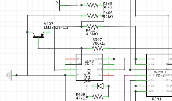
On 2017-Mar-19, at 4:01 PM, Adrian Graham via cctalk wrote:
> On 19/03/2017 19:59, bhilpert wrote:
>> On 2017-Mar-18, at 5:21 PM, Adrian Graham via cctalk wrote:
>>>
>>> 8085-based phone system weirdness continues and I'm beginning to wonder if
>>> the PSU rails are all coming up in time for RESET to go high - given there's
>>> 4116 DRAMs in there isn't there supposed to be a proper power up order?
>>>
>>> While I look at using a 20-pin ATX PSU to run this machine temporarily I
>>> need a safe way to reset the CPU rather than constantly power cycling. The
>>> RESET line comes from an ICL7611 op-amp via an MC14081B through pins 1-4 of
>>> a 74LS04 and I need to pull it low for longer than 3 clock cycles.
>>>
>>> I wish I had a schematic to show!
>>
>> Recalling the messages from December, it looked like proper operation of the
>> reset circuitry at power-up
>> expected the presence of the battery to power the reset circuitry with 12V
>> prior to the 5V bus coming up.
>>
>> It looks like you could add a reset switch to the unit by paralleling R406
>> (11K) with a NO pushbutton switch and ~ 4.7 uF cap (all 3 in parallel).
>> Closing the pushbutton switch simulates the absence of 5V. The cap provides a
>> little debounce delay, but may not even be necessary.
>
> I've just checked the image you're referring to and the resistor numbers are
> offset so it looks like R406 is the top one of three where it's actually the
> middle one. Here's an up-to-date version:
>
> http://www.binarydinosaurs.co.uk/STCExecutelResetOpamp.jpg
Yes, I did notice that in viewing, so it remains R406 / 11K / the one going to
ground, to parallel with a switch.