Hello William,

the output is:
root@beaglebone:/lib/firmware# ls /sys/devices/platform/ocp/
40300000.ocmcram          47400000.usb     48046000.timer     4819c000.i2c
                  48302000.epwmss  4a100000.ethernet  modalias
 ocp:P9_22_pinmux
40302000.ocmcram_nocache  48022000.serial  48048000.timer     481a0000.spi
                  48304000.epwmss  4a300000.pruss     ocp:l4_wkup@44c00000
 of_node
44e07000.gpio             48030000.spi     4804a000.timer
481aa000.serial                48310000.rng     4c000000.emif
ocp:P8_13_pinmux
     power
44e09000.serial           48038000.mcasp   4804c000.gpio      481ac000.gpio
                 49000000.edma    53100000.sham      ocp:P8_19_pinmux
 subsystem
44e0b000.i2c              4803c000.mcasp   48060000.mmc       481ae000.gpio
                 49800000.tptc    53500000.aes       ocp:P9_14_pinmux
 uevent
44e35000.wdt              48042000.timer   480c8000.mailbox
48200000.interrupt-controller  49900000.tptc    56000000.sgx       ocp:
P9_16_pinmux
44e3e000.rtc              48044000.timer   480ca000.spinlock
48300000.epwmss                49a00000.tptc    driver_override    ocp:
P9_21_pinmux
I compiled your overlay with this command:
dtc -O dtb -o /lib/firmware/univ-wph-00A0.dtbo -b 0 -@ /lib/firmware/univ-
wph-00A0.dts
Is that the correct way to do it?
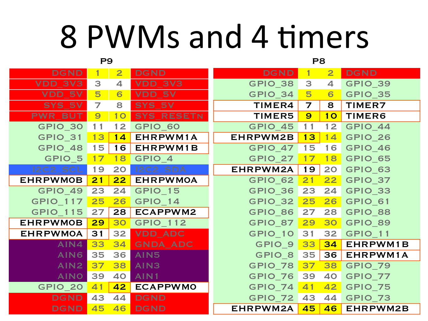
Regarding your question whether I used the correct pins: I set all pwm
outputs with the nested for commands described in the my last post and used
the oscilloscope to measure all the pwm pins given in this image
(http://beagleboard.org/static/images/cape-headers-pwm.png) against a GND
pin. So at least one of them should have caused some output on the
oscilloscope.
The oscilloscope is working correctly as it gives me 3.3V and 5V for P9_3
and P9_5.
Best regards
Phil
--
For more options, visit http://beagleboard.org/discuss
---
You received this message because you are subscribed to the Google Groups
"BeagleBoard" group.
To unsubscribe from this group and stop receiving emails from it, send an email
to [email protected].
To view this discussion on the web visit
https://groups.google.com/d/msgid/beagleboard/3a2fbf59-7fdb-4eed-b053-613629de12c0%40googlegroups.com.
For more options, visit https://groups.google.com/d/optout.